How To Configure the Grid: Simple Example
The configuration of grid load balancing can seem complex due to the many use cases supported by Edge. This article explains configuration through practical examples. Understanding the workflow before configuring your own grid is essential.
The example features a grid with a 40A installation current consisting of 4 chargepoints and an office building, protected by an energy meter GUARD.
What do you need to get started?
- Add the chargepoints to Edge
- The energy meter has been installed and configured
- Give every station their own recognizable name
Video Instructions
Grid Configuration
To specify the grid and how load balancing should be done we will need to go to the grid configuration-tab. The following image shows what the grid will look like when you open it for the first time.
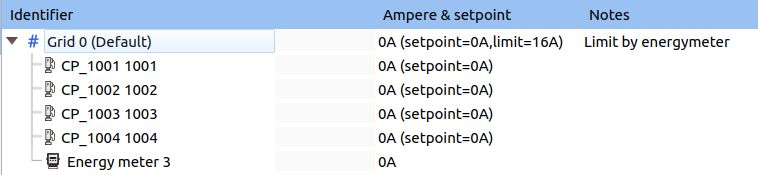
Every chargepoint and energy meter that is connected to Edge will be added to grid 0 by default. Grid 0 will have a default current of 16A.
Because every device is automatically added to grid 0 the only thing we need to change is the total current the grid can use. This is done in the following steps:
- Click the button: "Edit grid" on the right top of the screen.
- Click on "Grid 0 (Default)".
- Change the setting "Max current" to 40A so it matches our example.
- Optional: Give this grid a user-friendly name by changing the "Grid Identifier" to e.g. "Office Parking".
- Click the button: "Save changes".
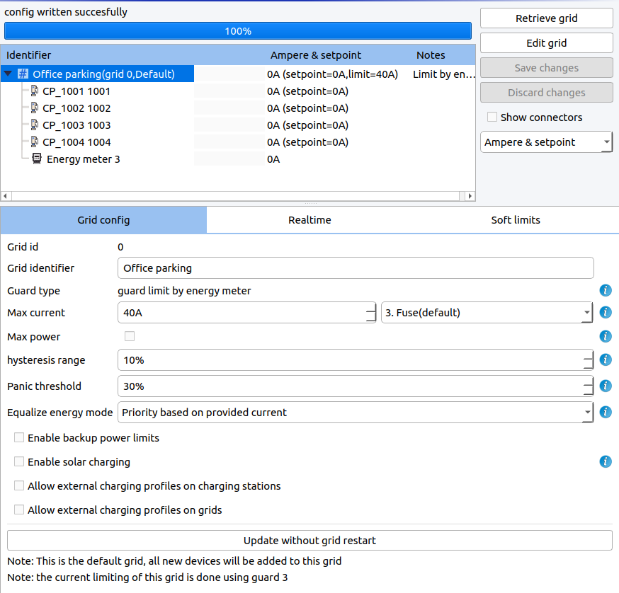
Configurable Options and Vocabulary
Here follows some information for all the options you will see during the config. Note that in 90% of the cases you will only have to configure the "Max current" and "Grid Identifier", and leave the other settings untouched.
- Grid ID: This ID matches the Grid you just selected. This ID is unique for each grid and is used to identify them. Grid 0 is the default grid where every new device will be automatically added.
- Grid Identifier: An optional user friendly custom name for the grid. This name will be shown in the overview instead of the Grid ID.
- Guard Type: This read-only field notifies you how the grid is protected against overcurrent. It is automatically set based on the presence of an energy meter and its configuration. The possible options are:
- Guard by energy meter: There is an energy meter configured as GUARD in this grid. The measurands from this energy meter are used to protect the grid.
- Grid Limit: There is no energy meter configured as GUARD. There is no protection against overcurrent in case of chargepoint malfunction or external loads.
- Max current: The maximum current that can be used by this grid. This current can be protected by using an energy meter as GUARD. Note that the current the chargepoints may consume can be more than "Max current" when there is a solar or battery installation in the same grid.
- Max power: optionally, specify a second limit in watts. This is often used for contracted capacity. While "Max current" limits on the highest phase, "Max power" allows 3-phase imbalance. Also, it is possible to choose between active power (kW) and apparent power (kVA).
- Fuse Type (Max current): This setting can be used to configure how the Edge loadbalancer should deal with the (lowest) limit. When a low number is chosen (soft limit, fuse), Edge will handle the limit in an agile way where Edge waits an extra second before responding when the limit is exceeded a little to filter out peeks/inrush load. When choosing a higher number (conservative), Edge will respond faster when exceeding the limit and will take longer to ramp up again. Also, the loadbalancer will remember unregulated load peeks and use this as an extra margin. The default configuration is "3. Fuse", as this is strict enough to not cause problems, but allows some little peeks over the limit as a fuse is always made to handle short moments of over current.
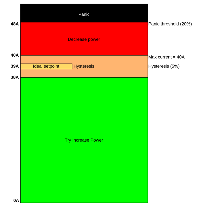
- Hysteresis range: The Hysteresis is a percentage of the Max current where the algorithm will not try to increase or decrease the power of the grid. This gives a small blind spot where Edge will not change the setpoint. See the image at the bottom of this article for a visualization.
- Panic threshold: The Panic threshold is a percentage above the Max current. When the current is between the Max current and the Panic current the algorithm will try to slow it down. When the current gets above the Panic current the algorithm will completely stop the entire grid once it gets reached. Be careful when selecting this value since a single current spike over this threshold will cause the grid to shut down and restart. See the image at the bottom of this article.
- Equalize energy mode: This setting determines how the priority between the chargepoints is divided, and thus how the power to the chargepoints will flow. The options are:
- Off: Every chargepoint will have the same priority at any time.
- Based on provided current (Default): The priority of the vehicles is determined based on how much power we made available for it (setpoint). The result is that if a vehicle does not use its provided current its priority will lower. At the end of the day every vehicle should have the same power provided to them.
- Based on used current: The priority of the vehicles is determined based on how much power they have used. The result is that vehicles that are not using power will get a higher priority.
- Export limit: Controls how much power Inverters and batteries may export to the grid. For more information see the article Export limits.
- Enable solar charging: allows for the solar charging functionality. For more information see the article Solar charging.
- Allow external charging profiles on chargepoints: Edge will take external OCPP 1.6 charge profiles into account which are sent to the chargepoints. Edge will execute the charging profile, it might choose to charge slower as Edge keeps the protection of the grid as its first priority. An overview of the active profiles can be found and edited in the "Soft limits" tab.
- Allow external charging profiles on grids: OCPP 1.6 Charge profiles that are sent to the Edge itself will be applied to the grid. The external limit can be found and edited in the "Soft limits" tab. Contact LMS Support if you want to use this functionality.
Simple example with the "Max current", "Panic" and "Hysteresis" settings
Here follows a simple example with the "Max current", "Panic" and "Hysteresis" settings. In this example we will show the results for the default settings where only the "Max current" has been changed to 40A. The "Panic" and "Hysteresis" will both scale on the max current since they are percentages.